Cornice Projection: How to Calculate and Fix It
Facade cornice projection is the distance by which a cornice stands out from the wall plane (or the cladding). It is set on the basis of architectural proportions and the building's scale and then checked by calculation: the greater the projection, the higher the cantilever moment on the fixing points and the more substantial the inserts, brackets and anchors must be.
The main criterion is a balance of three requirements: the cornice must shed water and be legible from the ground, be securely fixed against wind and snow, and not overload the substructure or wall. On multi-storey buildings the architect sets the projection and the structural engineer designs the fixing.
This article is for designers and clients who want to understand the logic behind the solution. All décor is covered in Architectural facade décor.
What projection is
Projection is measured horizontally from the wall plane (for a rainscreen facade, from the face of the cladding) to the most projecting point of the profile. Together with the profile height, it determines the proportions of the cornice and how it looks from different viewpoints.
Projection serves several functions:
• it sheds run-off beyond the wall plane;
• it casts a shadow that emphasises the horizontal and makes the profile legible;
• it visually completes the facade or part of it.
It is important to distinguish architectural projection (the visible profile) from structural projection: on a rainscreen facade the cornice is fixed through the substructure, and the actual lever arm from the wall to the cornice's centre of gravity is greater than the visible projection by the thickness of the insulation and air gap.
An example of the logic: if the visible projection of a cornice is several tens of centimetres and the insulation plus air gap adds as much again, the bracket works on a lever arm almost twice the visible projection. That is why on rainscreen facades even cornices that look small need the fixing detail to be calculated.
Standards and proportions
There is no single standard for the projection of a decorative cornice — it is an architectural decision. Guidelines are provided by:
• Classical order proportions. Treatises relate cornice projection and entablature height to the column module; in the classical tradition, the projection of a crowning cornice is comparable to its height. For a neoclassical facade these ratios are a starting point that is adapted to the number of storeys.
• Building scale and viewpoint. The higher a cornice is installed, the larger its profile and projection must be to be legible from the street.
• Drainage. The projection must be sufficient for water to drop from the drip clear of the elements below.
• Site constraints. Projections over pavements and site boundaries may be restricted by planning requirements.
Load requirements for facade elements are set by current Russian codes of practice (SP) on loads and actions, and fixing requirements for rainscreen systems by the documents for the specific facade system.
A typical mistake is transferring proportions from a low-rise building to a high-rise one without adaptation: a profile that works on a mansion becomes a thin line at 15th-floor level. The opposite mistake is excessive projection at lower levels, which looks oppressive and requires heavy fixings. The solution is found on a 3D model from real viewpoints, and the design department checks the chosen projection structurally before moulds are made.
Cantilever load
A cornice is a cantilever: it is supported by the wall on one side, and loads act on a lever arm. The main loads:
| Load | How it acts | What is taken into account |
|---|---|---|
| Dead load | Vertically, on the lever arm to the centre of gravity | Weight of the element and fixings |
| Snow and ice | Vertically, on the top surface | Snow region, fall, risk of ice build-up |
| Wind | Pressure and suction, including upward | Height, terrain type, corner zones |
| Imposed | Maintenance loads, ladders leaning on it | Client requirements |
The moment at the fixing point grows in proportion to the lever arm, so doubling the projection roughly doubles the bending moment from the same weight. For lightweight GFRC this is an advantage over stone: the same profile produces a smaller moment. Even so, large projections require calculation to current codes and, as a rule, a metal frame or cantilever brackets.
Calculations cover load combinations with partial safety factors and check not only the cornice itself but also the brackets, anchors and substrate.
Anchors and cast-in inserts
A facade cornice fixing consists of three links: cast-in inserts in the element → bracket or cantilever → anchor in the substrate.
• Cast-in inserts are placed in the GFRC during casting: plates, sockets, anchor loops of stainless or protected steel. Their position and number are determined by calculation; the element is strengthened around the inserts.
• Brackets are metal cantilevers that transfer the load to the floor slab or wall. A bracket-supported cornice is the main solution for large projections: the bracket takes the moment and the skin forms the profile.
• Anchors are selected according to the substrate material (concrete, brick, aerated concrete) and the results of on-site pull-out tests. In hollow brick and aerated concrete, anchor capacity is lower, so the aim is to transfer the load to the floor slabs.
The scheme must let the cornice move freely with temperature: some fixings carry load, others only restrain. Fixings in areas exposed to water and condensation are made corrosion-resistant.
Before installation starts, on-site pull-out tests of anchors in the substrate are carried out: their results confirm or adjust the design decisions. During installation each fixing is set to survey levels, and after installation the cornice line is checked along the full length of the facade.
Protecting the top
The top of a cornice is the surface most vulnerable to water. It receives rain, snow and meltwater from the roof. Solutions:
1. An outward fall on the top surface — so that water does not stand.
2. A metal flashing (polymer-coated galvanised steel, copper, aluminium) over the cornice, tucked into the wall under the cladding or into a joint.
3. Sealing the joints between cornice elements, or cover strips over the joints.
4. Water-repellent treatment of the GFRC surface.
5. Bird protection — deterrent systems are fitted on wide ledges where necessary.
On crowning cornices, snow and ice are also taken into account: without snow guards on the roof, snow may slide onto the cornice, so the roof and cornice detail are designed together.
The most common mistake is a flashing without enough width and without a drip: water runs off its edge onto the face of the cornice and leaves streaks. The flashing edge must project beyond the profile and be turned down.
Examples from TECHNOFORMA projects
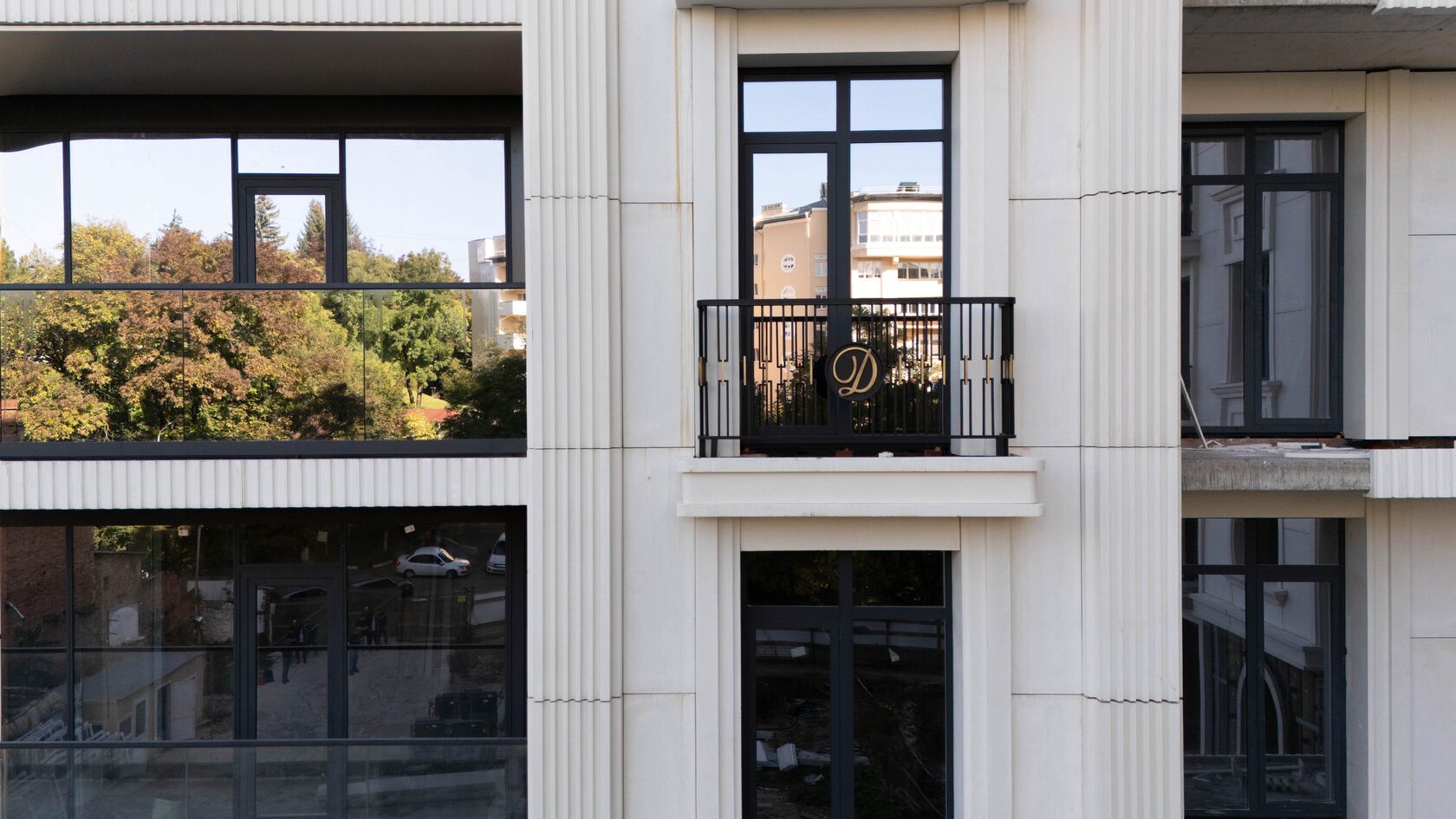
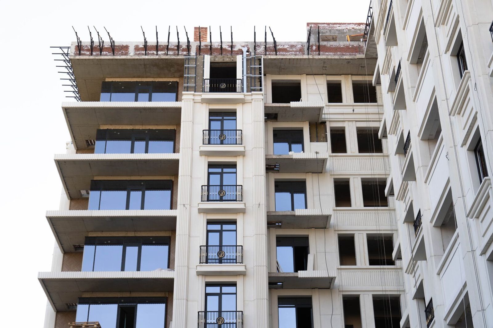
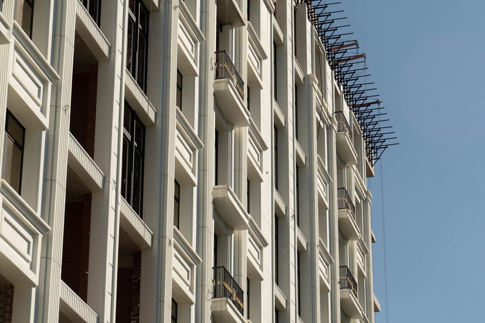
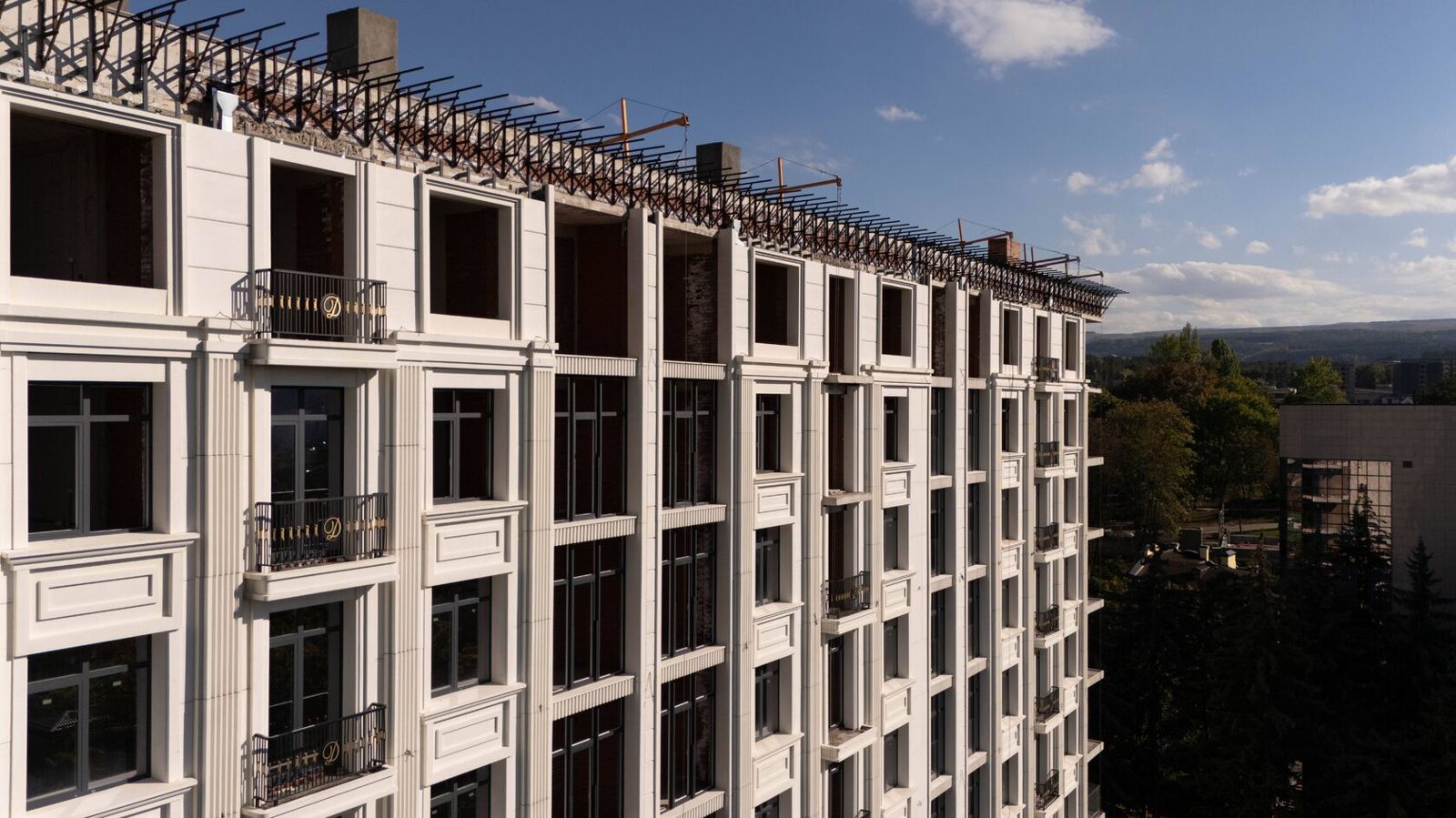
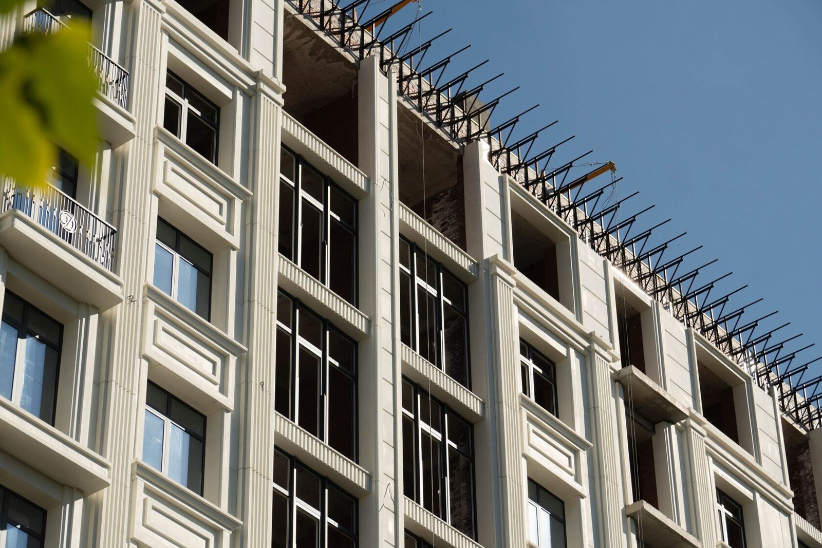
TECHNOFORMA designs GFRC cladding elements and installs them with its own installation division of more than 100 specialists. At Dominanta residential complex in Makhachkala (18 storeys) 14,000 m² of GFRC was installed, and at Alye Parusa residential complex (12 storeys, 4 buildings) — 20,000 m² with installation supervision.
All projects are in the TECHNOFORMA projects section. For smaller-scale horizontal divisions, see String courses and mouldings on the facade.
FAQ
How is a facade cornice fixed?
Via cast-in inserts in the element to brackets or cantilevers anchored into the floor slab or wall; the scheme is determined by calculation.
When is a bracket-supported cornice needed?
For large projections and weights: the metal bracket takes the cantilever moment while the GFRC skin forms the profile.
What should the projection of a facade cornice be?
There is no single standard: projection is set by the building's proportions and scale and checked by a fixing calculation.
What loads are considered when designing a cornice?
Dead load, snow and ice, wind (pressure and suction), imposed loads.
How do you protect the top of a cornice from water?
With an outward fall, a metal flashing, sealed joints and water-repellent treatment.