BIM and 3D Modelling of Facades
A facade BIM model is a three-dimensional information model in which every cladding, substructure and decorative element exists as an object with dimensions, material, fixing and a product mark. Drawings, specifications and element schedules are generated from it, and clashes with other parts of the design are checked in it.
The main benefit for a facade is not a nice picture but accuracy: decorative elements, cornices and window surrounds are coordinated with the architecture, structure and windows before production, and the product schedule is generated from the model automatically. For facades with complex glass fibre reinforced concrete (GFRC) and stone decoration this is especially important: each product is made to size.
This article is for architects, BIM managers and developers. Other design questions are covered in the section Facade Design and Selection.
Why BIM
For a facade, BIM solves several practical tasks that take longer and produce more errors with flat drawings:
| Task | In 2D drawings | In an information model |
|---|---|---|
| Element schedule | Counted manually from elevations | Generated from the model by product mark |
| Coordination with windows and structure | Cross-checking sheets from different disciplines | Clash checking in a shared model |
| Changes | All sheets corrected manually | Changing the model updates drawings and schedules |
| Visualising the appearance | Separate work by a visualiser | Views from the same model |
| Cladding layout | Separate diagrams for each elevation | Layout on a 3D surface, including corners and curves |
For the client, this means less rework on site and a more accurate estimate: quantities come from the model rather than a manual count. For technical supervision, it means a clear scheme against which installation is checked.
Modelling the Decoration
A 3D model of a decorated facade is built at several levels of detail:
• Concept: volumes, divisions, main decorative elements as simplified shapes — for approving the appearance and visualisation.
• Design: actual profiles of cornices and string courses, window surrounds, columns with capitals, cladding layout with joints.
• Working: each decorative element as a separate product with a mark, dimensions, positions of embedded parts and fixings, tied to the substructure.
For GFRC decoration, the model is especially useful at corners, on curved sections and where profiles intersect — where it is hard to understand the real shape of a junction from a flat drawing. The model shows how a cornice wraps around a corner, how a pilaster meets a band, and where a make-up piece is needed.
The design department of TECHNOFORMA Group includes designers and 3D visualisers: they prepare visualisations of the facade appearance and working documentation for the products and substructure. Data exchange formats with the lead designer (IFC, DWG, RVT) should be agreed at the start of the project.
Link to Production
The link between the model and production is what really distinguishes digital facade design from a simple 3D picture. The data path looks like this:
1. A product schedule with marks, dimensions and quantities is generated from the model.
2. A product drawing is issued for each mark: geometry, thickness, embedded parts, texture.
3. Master models and moulds are made from the drawings; for complex geometry, 3D data can be used to mill the models.
4. Products are marked in accordance with the model and layout.
5. On site, installers place elements according to the marking and an installation diagram taken from the same model.
When the design department and mould-making workshop are in the same company, this chain is shorter: questions of mould manufacturability are resolved in the model before the tooling is made. At TECHNOFORMA, models and moulds are made in the company's own mould-making workshops.
Clashes
Clashes are intersections between elements of different design disciplines that are not visible on flat drawings. Typical facade clashes include:
• a substructure bracket lands on the edge of a floor slab, in a masonry joint or where services pass through;
• a GFRC window surround overlaps the window frame or prevents a casement from opening;
• a cornice intersects the rainwater system or roofing elements;
• the decoration projection and insulation thickness do not fit between the wall and the sill;
• decoration obstructs the fixing of outdoor air-conditioning units, cameras or lighting;
• cladding fixings fall into a building movement joint.
Clash detection in the shared model is carried out before working documentation is issued. Every clash found at this stage is a detail not reworked on site and a product not thrown away.
Savings
Savings from digital facade design come from several sources:
• Less rework: clashes are resolved in the model, not on the scaffolding.
• Accurate schedule: exactly as many products are ordered as are needed, without large 'just in case' allowances.
• Standardisation: near-identical elements are easy to spot in the model and can be reduced to one type and size, cutting the number of moulds.
• Fast changes: adjusting the appearance updates drawings and schedules.
• Transparent estimate: quantities come from the model and are easy to check.
The cost of modelling pays back faster the more complex the facade and the more custom elements it has. For a simple panel facade, a 2D layout is enough; for a facade with elaborate decoration, curves and several materials, a 3D model is practically essential.
There are indirect savings too. Visualisations from the model help approve the appearance with the client and the architecture authority faster: instead of several rounds of sketch revisions, a single three-dimensional image is discussed. The model stays with the client after construction — it makes ordering a replacement for a damaged element easier, because the product's mark, dimensions and fixing are known.
It is important to keep the model up to date until construction is complete: changes made on site must be reflected in it; otherwise, by handover it no longer matches the built facade and loses its value for operation.
Examples from TECHNOFORMA Projects
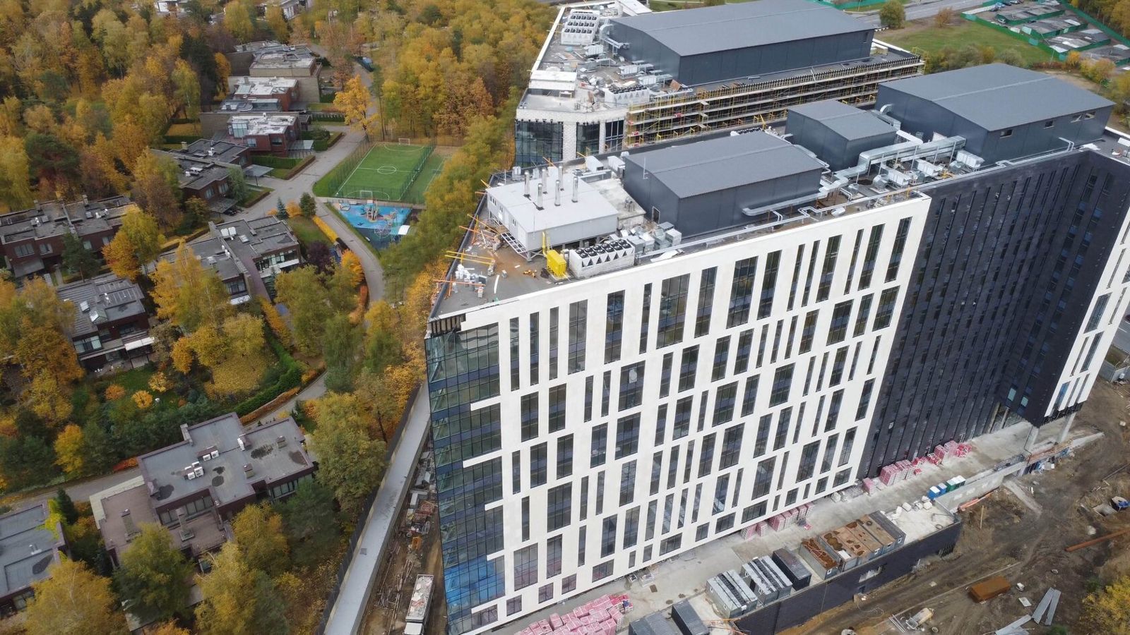
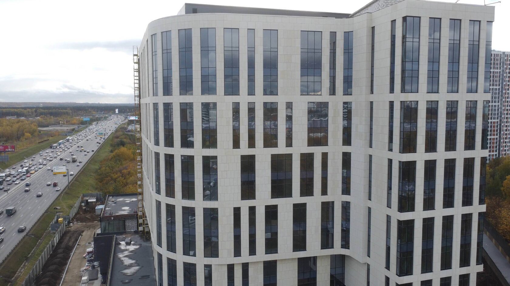
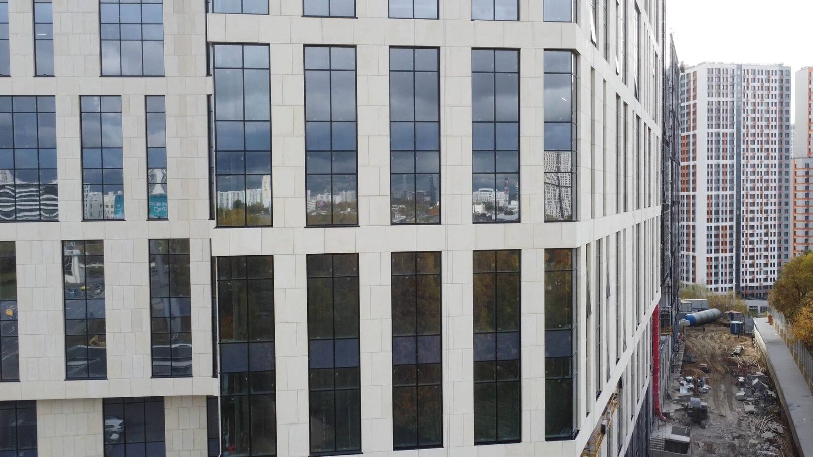
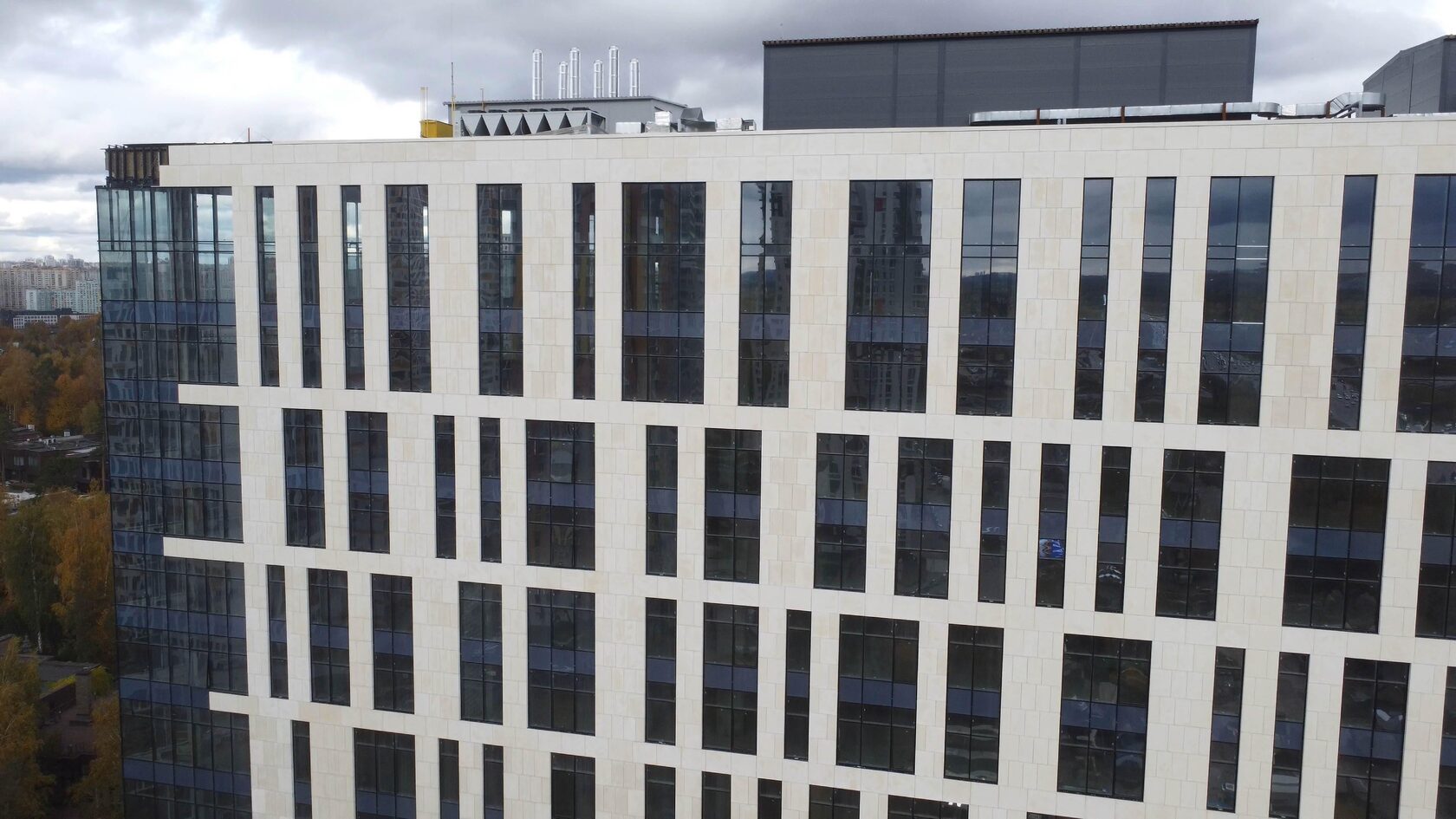
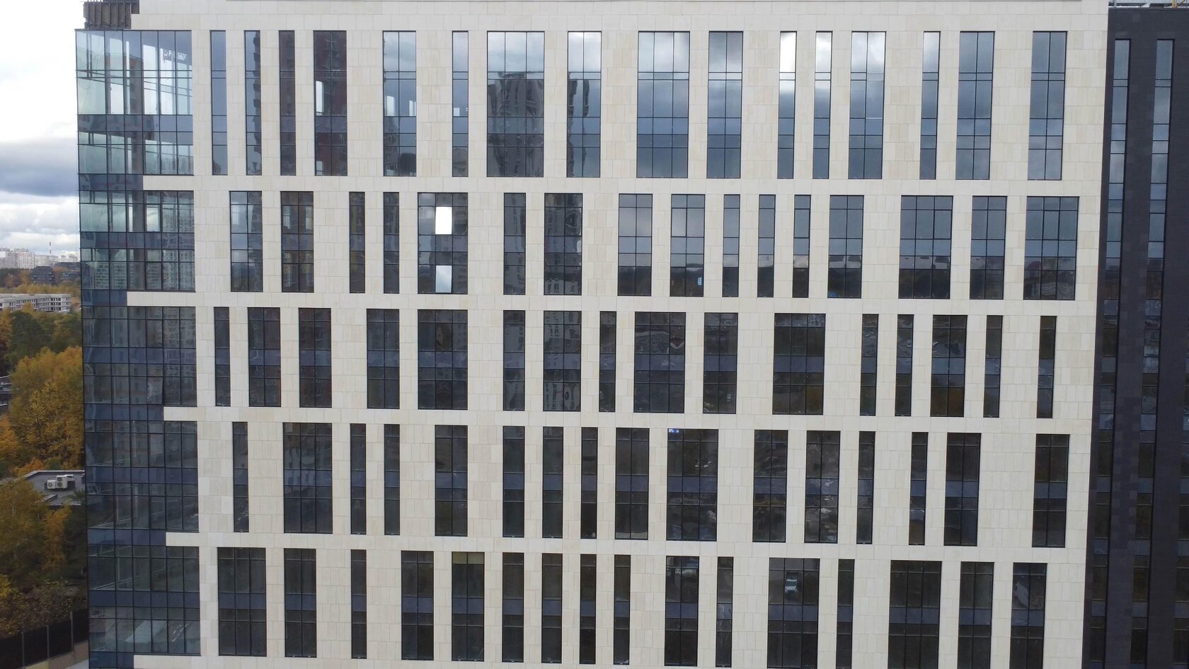
Detailed 3D work is especially needed on projects where decoration repeats across many buildings or where several materials meet on one facade. RUBLEVO BUSINESS PARK business centre in Moscow — 2 buildings of 12 storeys, 15,000 m² of GFRC and 5,000 m² of FRONTEK on a ventilated substructure; TECHNOFORMA Group carried out design and installation, 01.2023–04.2025.
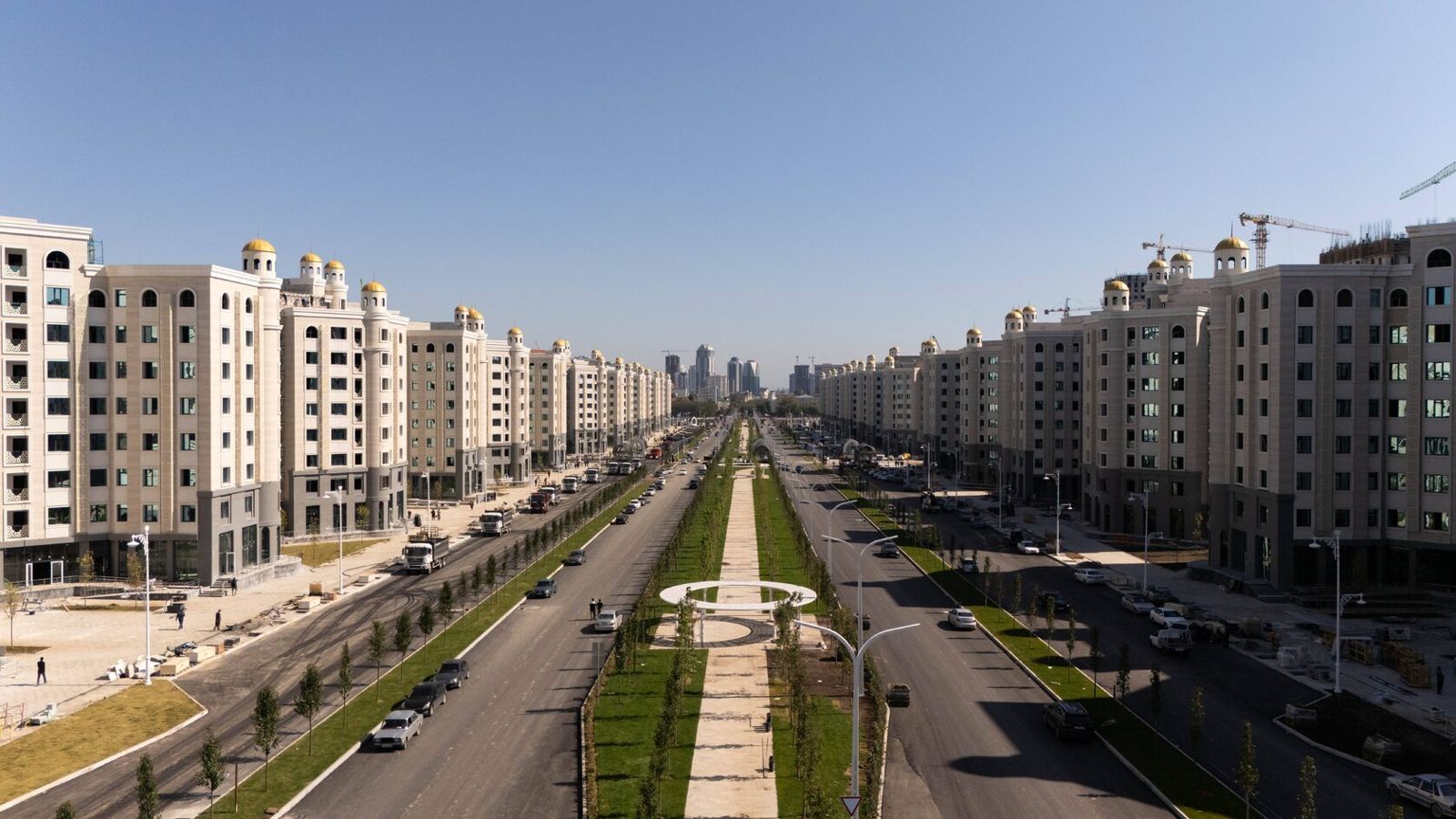
The Al-Qasr hotel complex — 4 buildings, 24,000 m² of GFRC cladding. Other projects are in the section TECHNOFORMA projects. How the design is controlled on site is explained in the article Design Supervision of Facade Works.
FAQ
What does BIM offer for facade design?
An accurate element schedule, clash checking with other disciplines, fast changes and visualisation from a single model.
Why is a 3D model of a decorated facade needed?
To see the real shape of junctions at corners and curves, coordinate decoration with windows and the substructure, and pass accurate data to production.
Which clashes are most often found on facades?
Brackets on the edge of a floor slab, decoration on a window frame, a cornice intersecting a downpipe, not enough space between insulation and sill.
Is BIM needed for a simple facade?
For a facade of uniform panels, a 2D layout is often enough; for complex decoration and several materials, a 3D model is justified.