Facade Design: Stages and Documents
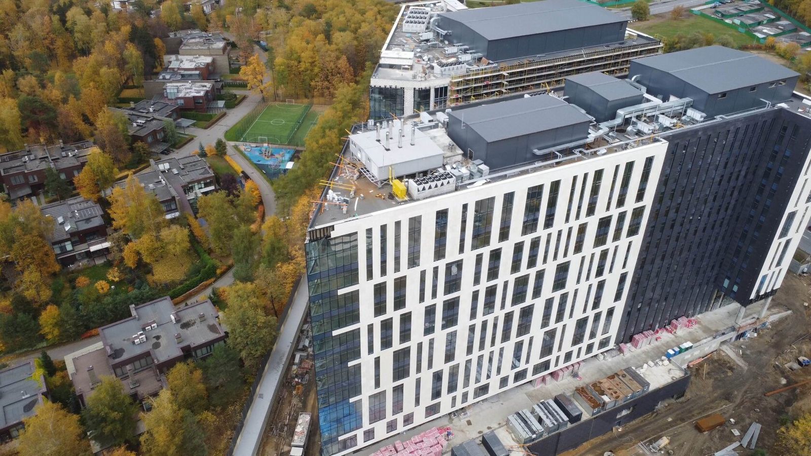
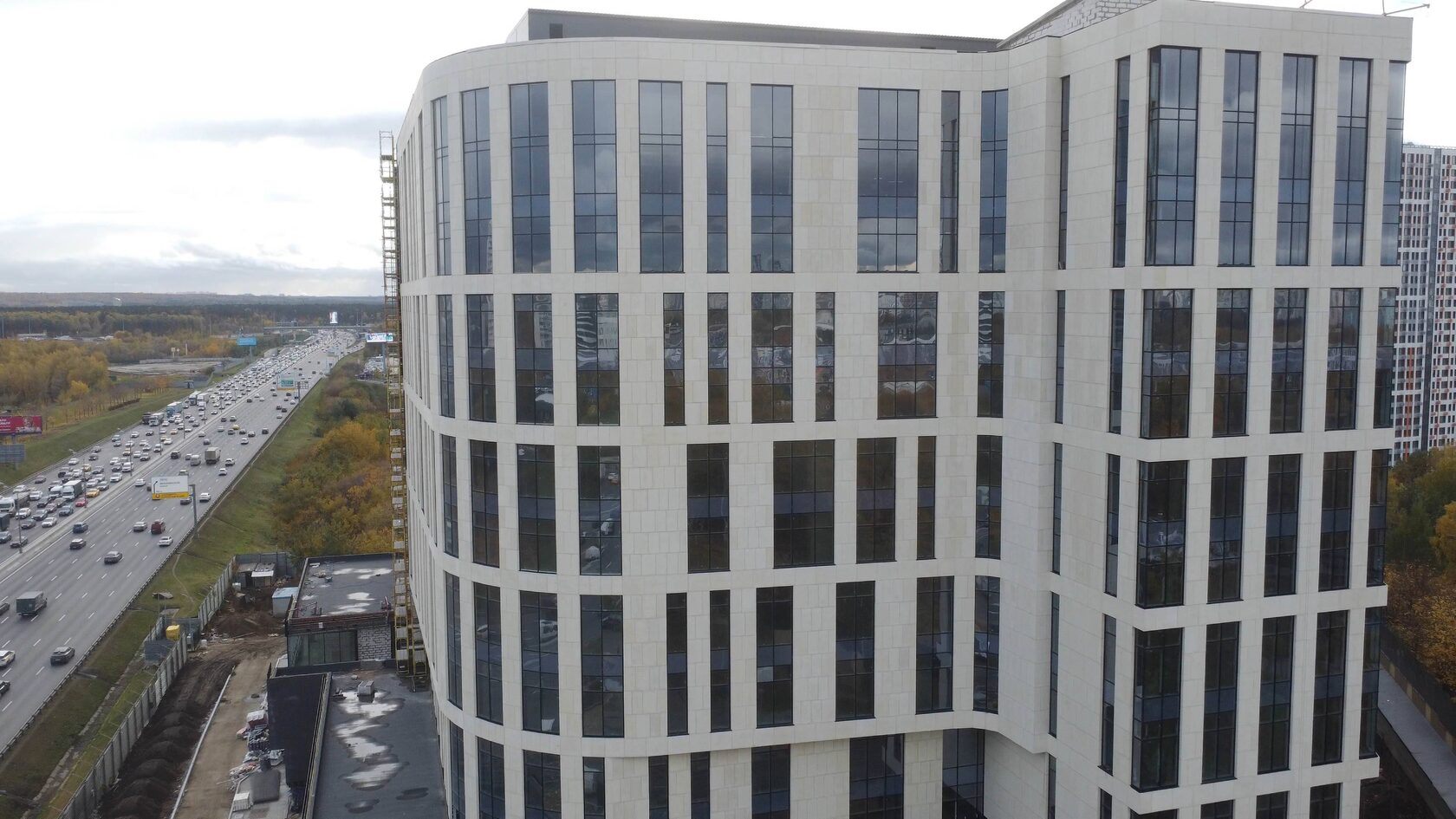
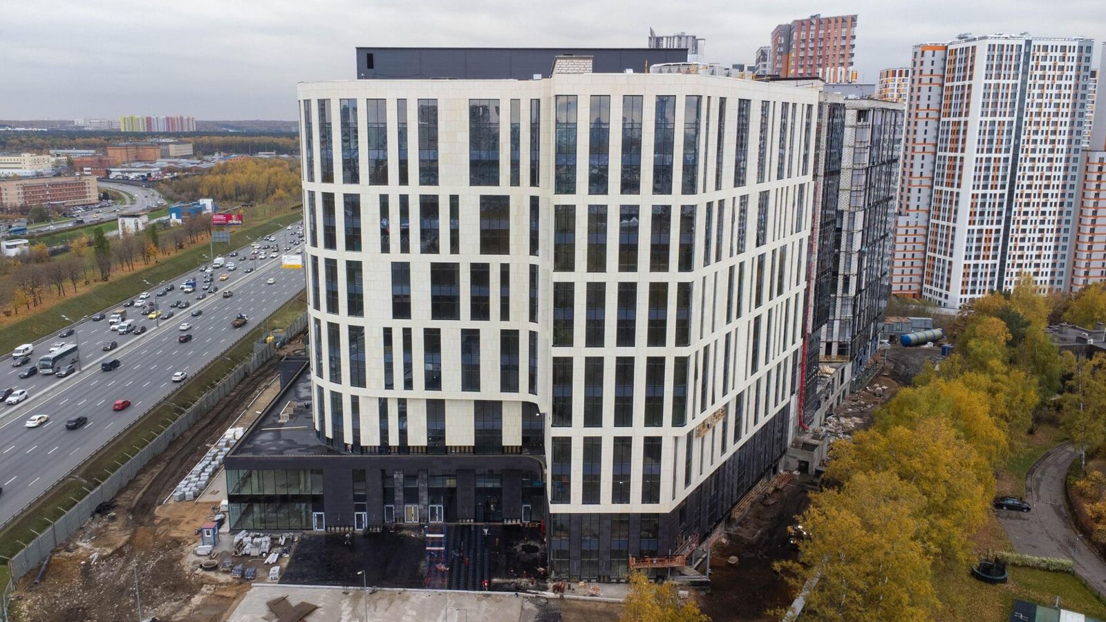
Facade design is the development of a set of solutions and documents from which the facade will be manufactured and installed: from the architectural concept and choice of materials to working drawings of the substructure, cladding layout, details and specifications. For a ventilated rainscreen facade the design also includes calculations: wind load, cladding weight, anchor capacity, thermal performance.
The main criterion of a good design is that it can be built without improvisation on the scaffold. If junctions, reveals and parapets are not detailed, installers resolve them on site, and that is exactly where leaks, cracks and efflorescence later appear.
This article is for developers, general contractors, client-side technical managers and architects planning the schedule and budget of facade works. At TECHNOFORMA the design department consists of 12 designers led by two architects, as well as 3D visualisers; the design is developed together with manufacturing and installation. More on selection and design is in the section Facade design and selection.
Stages
Facade design usually follows this sequence:
1. Collecting input data. The architectural design or a survey of the existing building, wall structure, construction area (wind, snow, climate), client and regulatory requirements.
2. Concept. The image of the facade, articulation, materials, colours; sketches and 3D visualisations of several options.
3. System selection. Cladding type, substructure, insulation, fixing method, with fire safety requirements checked for the building's height and class.
4. Calculations. Structural calculation of the substructure and fixings, thermal calculation, checking the load-bearing capacity of the substrate (often with pull-out tests of anchors on the wall).
5. Working documentation. Architectural drawings of the facade, shop drawings of the substructure, cladding layout, details, specifications.
6. Production documentation. Product drawings: for GFRC these are models and moulds, for stone cutting and finishing sheets.
7. Designer supervision during installation and revision of the documentation to reflect actual deviations.
At TECHNOFORMA, after the design department, the work is taken over by the company's own mould shops (models and moulds are made in-house), production with quality control, logistics and installation teams, so the transition from drawing to product happens within one company.
Documentation package
The documentation package depends on the stage and type of facade. For a ventilated rainscreen facade a typical set is:
| Document | Contents | Who needs it |
|---|---|---|
| Explanatory note | Description of the system, materials, input data, decisions taken | Client, state expert review, technical supervision |
| Facade elevations | Cladding layout, colours, materials, references to axes and levels | Architect, production, installation |
| Substructure drawings (shop drawings) | Brackets, rails, spacing, fixings, anchoring plans | Substructure production, installation |
| Details | Reveals, sills, corners, parapets, plinth, movement joints, fire barriers | Installation, technical supervision |
| Calculations | Structural, thermal, anchor test results | State expert review, technical supervision |
| Specifications | List of products, fixings and insulation with quantities | Procurement, estimators |
| Product drawings | For GFRC, stone and non-standard elements | Production |
For buildings whose appearance is approved by city authorities, materials on the architectural appearance are added: visualisations, colour scheme, finishes schedule.
Architectural drawings and substructure shop drawings
The architectural section (AR in Russian practice) answers the question of what the facade should look like: articulation, proportions, materials, colours, architectural details, levels. It is based on the concept and, for buildings subject to state expert review, forms part of the design documentation.
The shop drawings for the metal structures (KMD in Russian practice) answer the question of how it is held up: detailing of the substructure, every bracket, rail, clip and anchor, their position and spacing, assembly diagrams. The substructure is manufactured and assembled from these drawings.
• The architectural section sets the cladding layout; the shop drawings adapt the rail grid to it.
• The architectural section fixes the material and panel thickness; the shop drawings calculate the loads and select the fixings.
• The architectural section shows projecting elements (cornices, pilasters, bay windows); the shop drawings resolve their embeds and brackets.
If the two sections are produced by different organisations without coordination, discrepancies arise: a joint does not land on a rail, a cornice has nothing to hang on. When both are developed by one team together with the cladding manufacturer, there are fewer such discrepancies.
Approvals
Facade design approvals take place at several levels:
• With the client and architect: concept, materials, samples, visualisations, layout. Decisions are recorded in minutes.
• With the lead designer: compatibility with the structure, building services, windows, roof.
• State expert review: for projects whose design documentation is subject to review, facade solutions are reviewed as part of the design.
• City authorities: in some cities, including Moscow, the appearance of a facade is approved separately (architectural appearance, facade passport, etc.). The procedure and documents are set by each city's regulations.
• Technical supervision: checks that installation complies with the working documentation.
Changes after approval (a different material, colour or articulation) often require re-approval, so materials are best chosen and checked on samples before documents are submitted.
Timeframes
The time needed to design a facade depends on the area and complexity of the building, the number of unique details and elements, the completeness of input data and the number of approval iterations. There is no universal figure; the timeframe is set for each project after analysing the input data.
What really speeds up a design:
• a full set of input data at the start: architectural design, structure, survey results;
• an early decision on materials and system: every revision sets back the shop drawings and layout;
• parallel work: while the working documentation is in progress, production prepares models and moulds for standard GFRC (glass fibre reinforced concrete) elements;
• one team for architectural drawings, shop drawings and products: fewer letters and less waiting for replies.
For large projects, the design is split into phases by building or facade, so that installation of the first sections can start before the design of the whole building is finished.
Examples from TECHNOFORMA projects
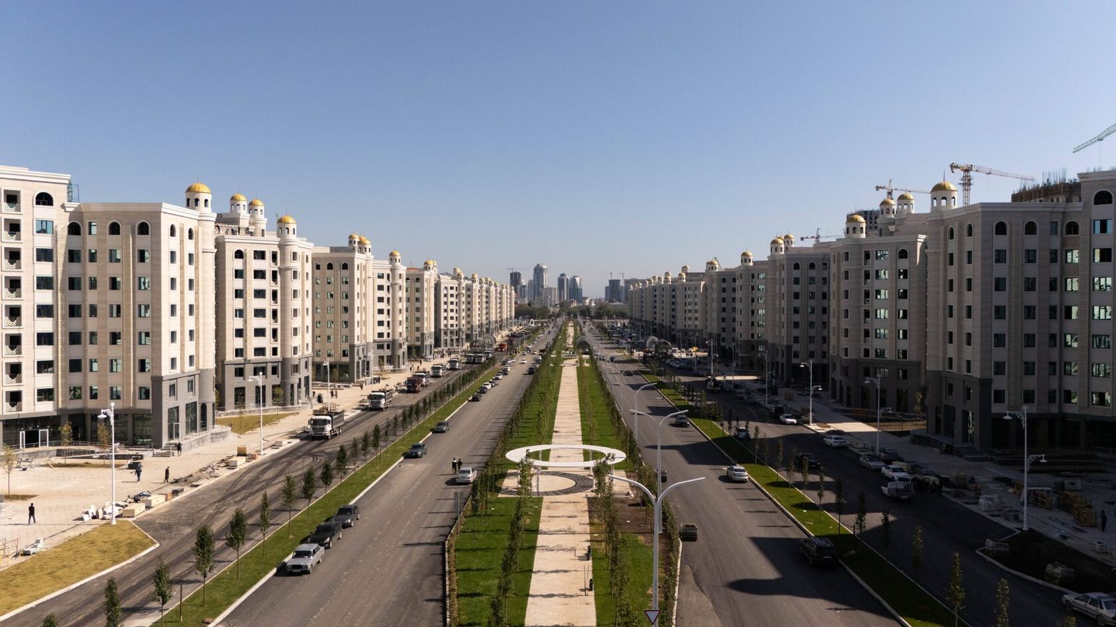
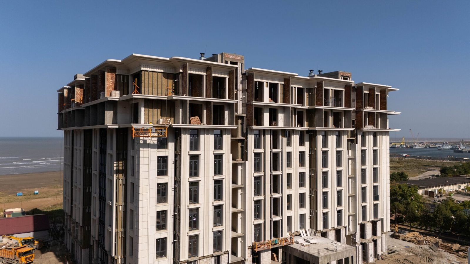
On all TECHNOFORMA projects published on the website, the company carried out the design. An example of a large residential project is the Dubai Houses residential complex in Grozny: 30 nine-storey buildings, 70,000 m² of GFRC, design and installation in 2025. An example of a public building is Chechen State University: 12,000 m² of GFRC, design and installation supervision.
Other projects are in the TECHNOFORMA projects section. Where a design begins is covered in Facade architectural concept: where a project begins.
FAQ
What does a facade design include?
An explanatory note, elevations with the cladding layout, substructure shop drawings, details, calculations, specifications and product drawings. For city approvals, visualisations and a colour scheme.
Who develops the facade design?
The lead designer as part of the architectural section, or a specialist facade company. TECHNOFORMA develops the design with its own design department, working together with production and installation.
How long does a facade design take?
It depends on the area, complexity and completeness of input data. The timeframe is set for each project; an early choice of materials and a full set of input data speed up the work.
Can a ventilated facade be installed without a design?
No. Without calculations and shop drawings it is impossible to confirm that the fixings are reliable and that fire requirements are met, and details are improvised on site with a risk of leaks.