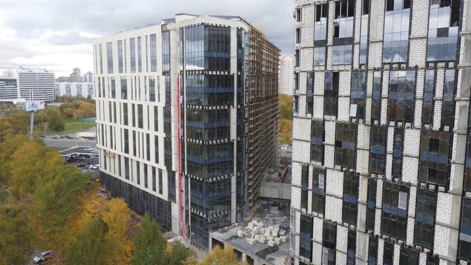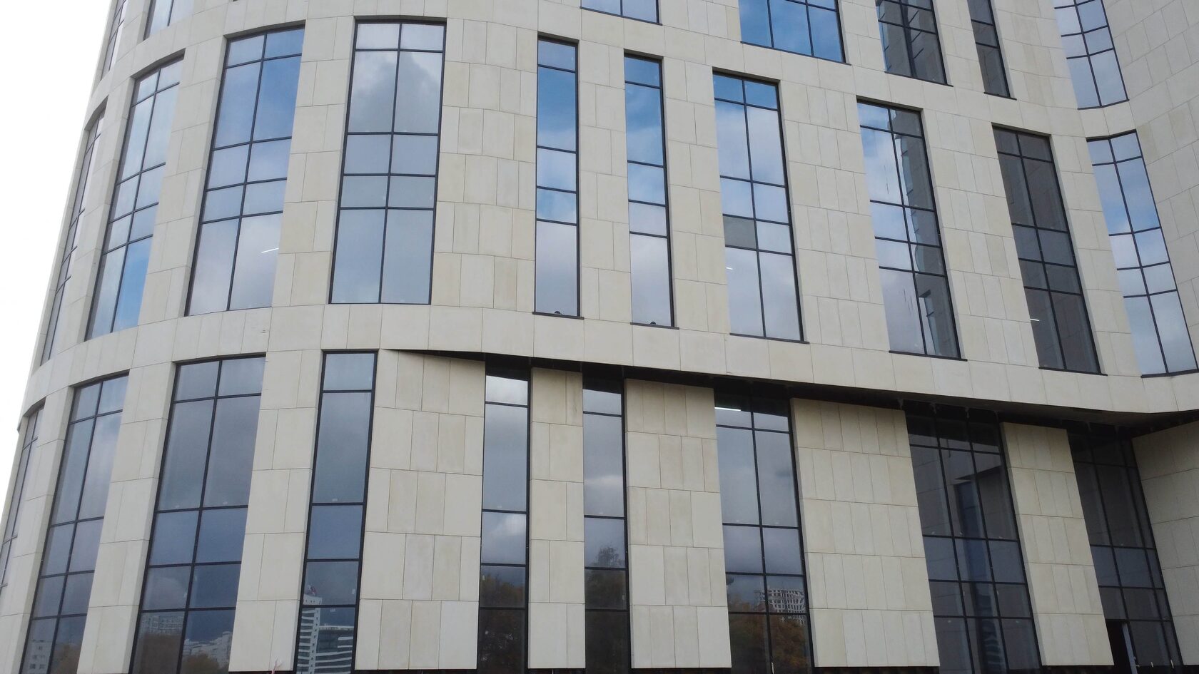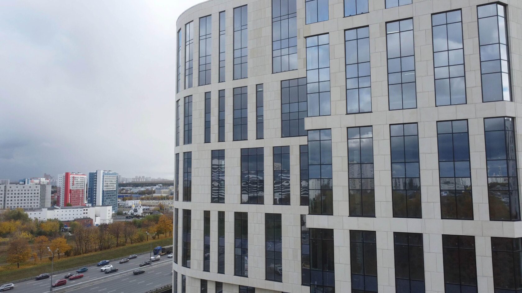
Anchor Pull-Out Testing Before Facade Installation
An anchor pull-out test is an on-site check of the load-bearing capacity of anchor fixings in the wall of a specific building. The anchor is installed in the substrate exactly as during installation and loaded axially with a portable tester up to a set load or to failure, and the maximum value is recorded.
The key criterion is that tests are carried out before the rainscreen facade working drawings are issued, at a sufficient number of points and in different wall zones, and the results are documented in a report. Without them, the substructure calculation relies on the anchor's published data, which may be unreliable for a real wall, especially a hollow or old one. The procedure is needed by general contractors, designers and technical supervisors in new construction and refurbishment.
The role of anchors in the overall system is in the Ventilated rainscreen facades section.
Why test
The anchor transfers the entire load from the cladding and wind to the wall. If it pulls out or breaks the substrate, the failure affects the bracket, the rail and the cladding elements above it.
• The anchor's data sheet gives values for a reference substrate — concrete of a certain class or brick of a certain grade. The real wall may differ.
• Masonry is non-uniform: voids, joints, low-strength mortar, aerated concrete of varying density.
• In refurbishment the wall's properties are often completely unknown.
• The substructure calculation requires the anchor's design load-bearing capacity — it is determined from test results with reduction factors.
Tests make it possible to choose the anchor type, embedment depth and bracket spacing on a sound basis. The economics look like this: an extra anchor on every bracket costs more than a day of testing, and an error in the other direction costs more than the whole facade.
Tests are especially important for heavy claddings — natural stone and large GFRC elements, where the vertical load on the anchor is high — and on tall buildings with high wind suction.
Test method
The test method is determined by regulatory documents and the anchor manufacturer's recommendations; the procedure is set out in a test programme.
1. Choosing locations. Test points are distributed across facades, floors and substrate types: typical masonry, zones near openings, floor slabs, areas with visible defects.
2. Installing anchors. The same anchors, drill bit, depth and drilling mode as in installation. For hollow materials — drilling without hammer action.
3. Loading. A tester with a support that does not restrict failure of the substrate around the anchor applies axial force in steps or continuously.
4. Recording the result. Maximum force and failure mode: anchor pull-out, cone failure of the substrate, steel failure, slippage.
5. Processing. The mean value, scatter and design load-bearing capacity are determined for the series.
The number of tests depends on the facade area and the non-uniformity of the substrate; each substrate type requires a separate series.
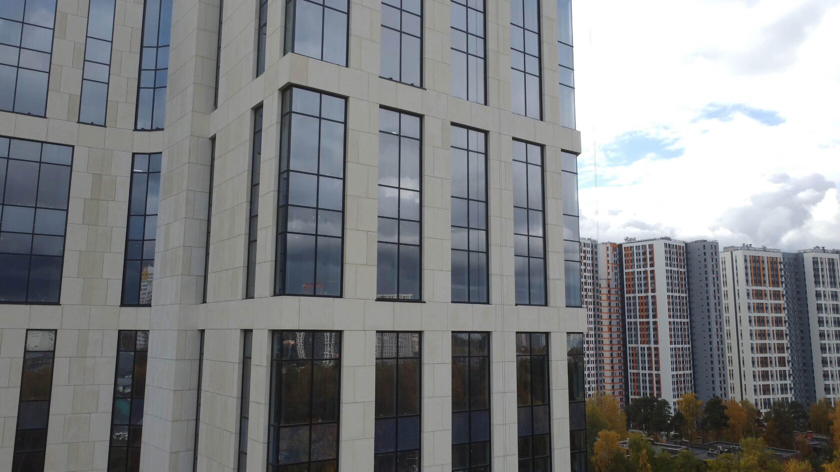
Test report
The report is the document on which the designer bases decisions. It must contain:
• the project, date, tester, equipment used and its calibration details;
• anchor type and size, drilling diameter and depth;
• substrate type and a layout of test points;
• the result for each point: force, failure mode;
• statistical processing and the design load-bearing capacity;
• conclusions and recommendations on anchor use.
The report is attached to the substructure calculation and to the as-built documentation. At acceptance, technical supervision checks that exactly the tested anchors have been used on site.
In addition to pre-design tests, on large projects proof tests are carried out during installation: selected installed anchors are loaded to a proof load without failure. This checks installation quality — correct drilling, hole cleaning, setting depth — and its results are also documented in a report and attached to the concealed works records for the brackets.
Substrate types
Results depend heavily on the substrate.
| Substrate | Characteristics | Typical solutions |
|---|---|---|
| Cast-in-situ reinforced concrete | High and consistent load-bearing capacity | Expansion and chemical anchors |
| Solid brick | Good load-bearing capacity; mortar quality matters | Expansion anchors, checking that they land in the brick body |
| Hollow brick, ceramic blocks | Low and inconsistent values | Anchors for hollow materials, chemical anchors with mesh sleeves, fixing to floor slabs |
| Aerated concrete | Low strength, depends on density | Special anchors for cellular concrete, moving load-bearing brackets to floor slabs |
| Old masonry | Non-uniformity, weathered mortar | Extended test programme, sometimes strengthening |
A single building often has several substrates: a concrete frame with block infill, brick sections, floor slabs. Tests are carried out for each of them, and the design specifies which anchor is used in which material. The installer on the scaffolding needs this information in a clear form — on the bracket layout drawing with zones marked — otherwise an anchor meant for concrete will end up in a hollow block.
If values are low
Low results are not a death sentence for the facade but input data for the design.
• Change the anchor type — chemical instead of expansion, or a special anchor for hollow materials.
• Increase embedment depth if the wall thickness allows.
• Add anchors per bracket or reduce bracket spacing.
• Move load-bearing brackets to floor slabs and concrete elements, leaving only support brackets on the wall.
• Use a slab-to-slab scheme — a substructure bearing on the floor slabs.
• Use lighter cladding if other measures do not work.
After the solution is changed, the chosen anchor is retested. All solutions are agreed with the designer and reflected in the working drawings. The earlier the results are obtained, the cheaper the correction: at the design stage it is a recalculation, at the installation stage it is idle crews and re-ordering fasteners.
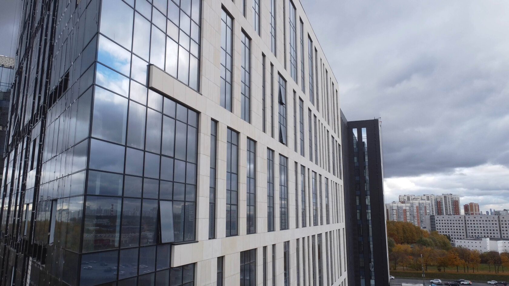
Examples from TECHNOFORMA projects
TECHNOFORMA carries out construction and installation work with its own installation teams of more than 100 specialists; the substructure is designed by the company's own design department. TECHNOFORMA projects include buildings with various substrates and loads: for example, the Triumph residential complex in Makhachkala (12 storeys, 11,500 m² of GFRC) and the Bogatyreva residential complex (14 storeys, 5,000 m² of GFRC) — both with facade design and installation by the company.
How much a complete rainscreen facade costs and what items go into the estimate is explained in "What makes up the cost of a ventilated facade".
FAQ
Why carry out anchor pull-out tests?
To determine the actual load-bearing capacity of anchors in the wall of a specific building and calculate the rainscreen substructure on that basis.
When are anchor tests carried out?
Before the working drawings are issued — at the survey stage. They are repeated if the anchor or substrate changes.
How many test points are needed?
It depends on the wall area and its non-uniformity; a separate series is carried out for each substrate type. The number is set by the test programme.
What should be done if an anchor in aerated concrete shows low pull-out values?
Change the anchor type, increase the number of anchors or move load-bearing brackets to the floor slabs, and repeat the tests.
Who can carry out anchor tests?
The anchor manufacturer, a laboratory or an installation company with calibrated equipment; the result is documented in a report.