Ventilated Facade Calculation: Loads, Wind, Bracket Spacing
Ventilated facade calculation is the structural design of the substructure for the cladding's self-weight, wind pressure and suction and thermal effects, with verification of the load-bearing capacity of brackets, rails, fasteners and anchors in the specific substrate. The result is the spacing of brackets and rails and the types of elements and anchors for each facade zone.
The key to a correct calculation is real input data: actual cladding weight, the building's region and height, and on-site anchor test results. A standard "catalogue" spacing without calculation is not always suitable, especially for heavy claddings — stone and GFRC. This article is for designers, reviewers, technical supervisors and clients checking a rainscreen facade design.
The general logic of the systems is in the Ventilated rainscreen facades section.
Input data
The calculation starts with collecting input data. An error at this stage carries over into all subsequent results.
• Building geometry: height, plan dimensions, shape, projections, parapets, corners.
• Construction region: wind zone, terrain type (open, urban), and for some regions seismicity.
• Substrate: wall material (cast-in-situ concrete, brick, aerated concrete, hollow blocks), thickness, position of floor slabs.
• Cladding: material, format, thickness, weight per element and per square metre, fixing method.
• Substructure: the chosen system, its album of technical solutions and element properties.
• Insulation and ventilation gap: these determine the bracket offset and hence the bending moment.
• Anchor pull-out test results in different facade zones.
For bespoke elements — cornices, GFRC pilasters, large stone slabs — working drawings with weight and centre of gravity position are needed: without them the connection cannot be calculated.
Wind loads
Wind load is the main variable load on a rainscreen facade. In Russia it is determined under code of practice SP 20.13330 "Loads and Actions".
• Characteristic wind pressure — by the construction wind zone.
• Height and terrain type — pressure increases with height; it is higher in open terrain than in dense urban areas.
• Aerodynamic coefficients — account for building shape. The facade is subject not only to pressure but also to suction; at corners and parapets peak suction is considerably higher than in the middle of the wall.
• Dynamic (gust) component — for tall buildings.
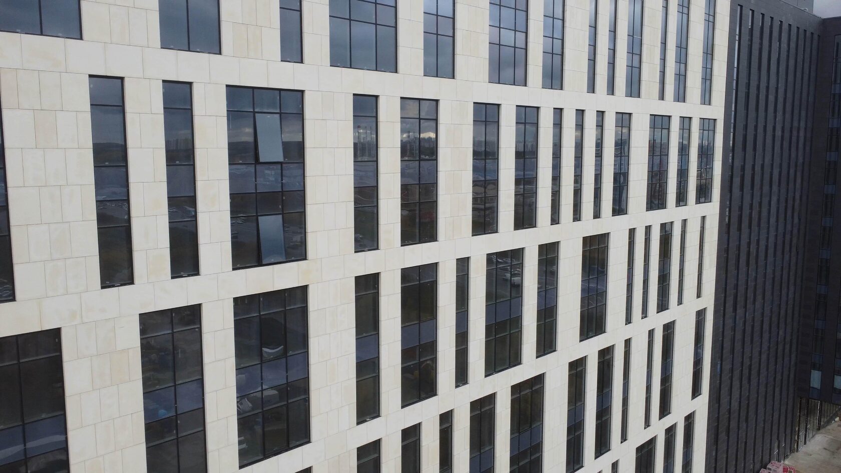
That is why the facade is divided into zones: the typical area, corner and edge zones, and upper floors. In edge zones, bracket and rail spacing is usually closer and cladding fixings more frequent. The simplification "one spacing for the whole facade" either wastes metal in the typical zone or underestimates the load at corners.
Cladding weight
The cladding's self-weight is a permanent load. It creates a bending moment in the bracket proportional to the offset, so thick insulation combined with heavy cladding is a demanding combination.
| Cladding | Approximate weight, kg/m² | Comment |
|---|---|---|
| Composite and metal cassettes | less than 10 | Wind is the governing load |
| Fibre cement boards | about 12–25 | Depends on thickness and density |
| Porcelain stoneware 10–12 mm | about 25–30 | Plus clips and profiles |
| GFRC | depends on the element | Thin-walled panels with a frame; for architectural elements — from drawings |
| Natural stone 30 mm | about 80–90 | For granite; a thicker slab is proportionally heavier |
The values are approximate; the calculation uses the weight from the product passport or working drawings. For TECHNOFORMA GFRC, the weight of each element is determined in the manufacturer's working drawings and passed to the substructure calculation — product and substructure design are done in the same loop.
Anchor capacity
The anchor is the weakest link in the system if the substrate quality is unknown. Anchor load-bearing capacity depends on wall material, strength, embedment depth, edge distance and spacing between anchors.
• For concrete and solid brick, the anchor manufacturer's published values are a guideline, but they are confirmed on site.
• For hollow blocks, aerated concrete and old masonry, published values are unreliable — only a pull-out test is decisive.
• The design value is taken with reduction factors applied to the test results.
If the load-bearing capacity is low, the number of anchors is increased, their type is changed (chemical anchor, anchor for hollow materials), or load-bearing brackets are moved to the floor slabs. Each of these solutions changes the layout, so tests are carried out before the working drawings are issued.
Calculation output
The output of the calculation is a section of the rainscreen facade design that includes:
• bracket layout schemes by zone, with vertical and horizontal spacing;
• types of load-bearing and support brackets, rails and fasteners;
• anchor types and required load-bearing capacity;
• strength and deflection checks of substructure elements;
• fixing details for the cladding and bespoke elements;
• instructions for inspection during installation.
Rainscreen bracket spacing is not a fixed value: it may differ by height and zone on the same building. Typical vertical values for the typical zone are around 0.6–1.2 m, less in corner zones; final values come only from calculation.
Besides strength, the calculation checks deformations. Rail deflection between brackets is limited so that the cladding plane does not wander and joints do not open. Thermal expansion of rails is taken into account when setting profile length and joint gaps: an aluminium rail several metres long changes length by several millimetres between winter and summer, and if rigid fixing prevents this, additional forces arise in the connections.
Checking the calculation during design review and technical supervision usually comes down to a few questions: where the cladding weight and wind zone came from, whether edge zones are accounted for, whether there are anchor test reports, and whether the elements in the calculation match the system album. If even one question has no answer, the calculation should be sent back for revision before installation starts.
Examples from TECHNOFORMA projects
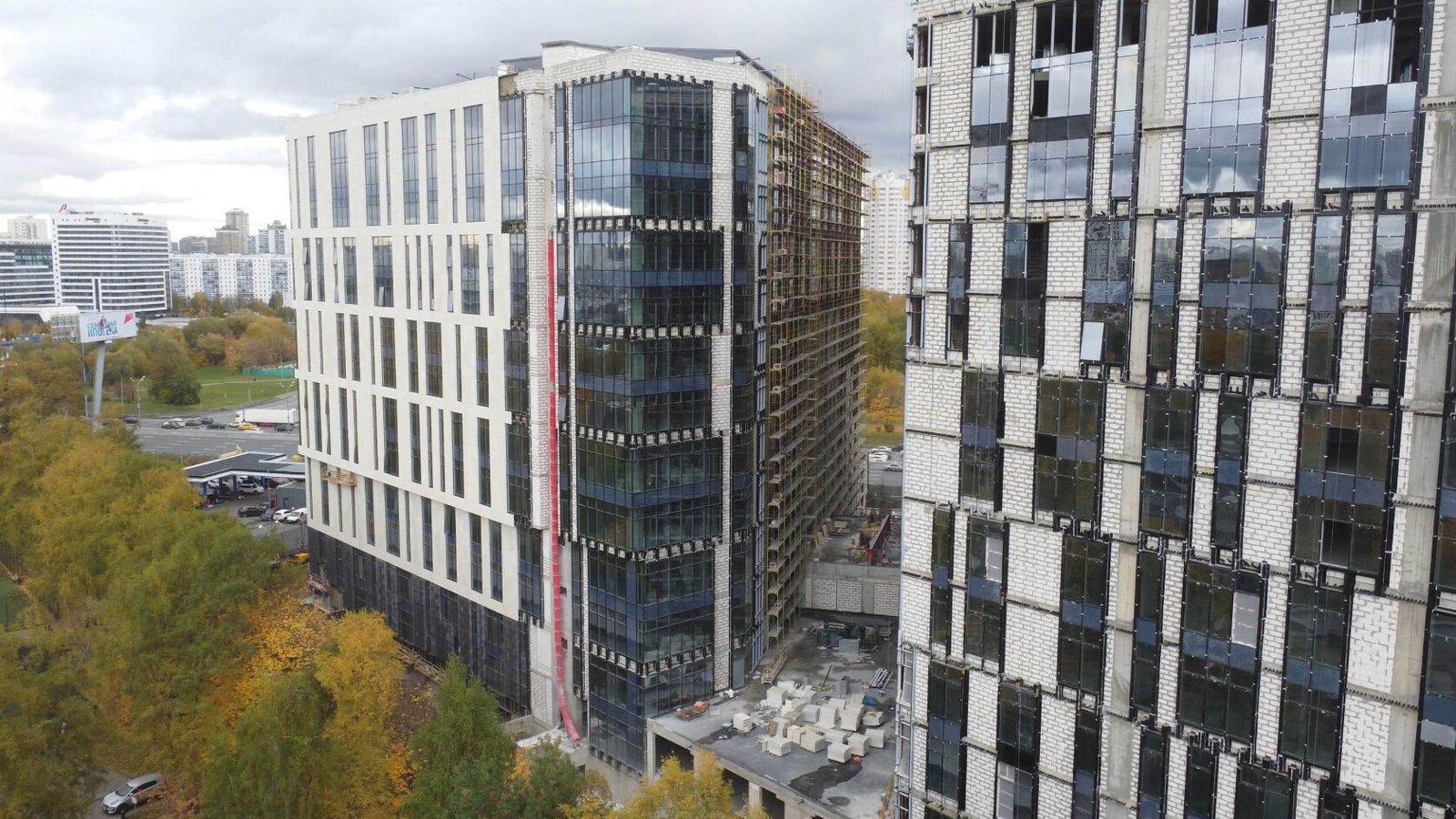
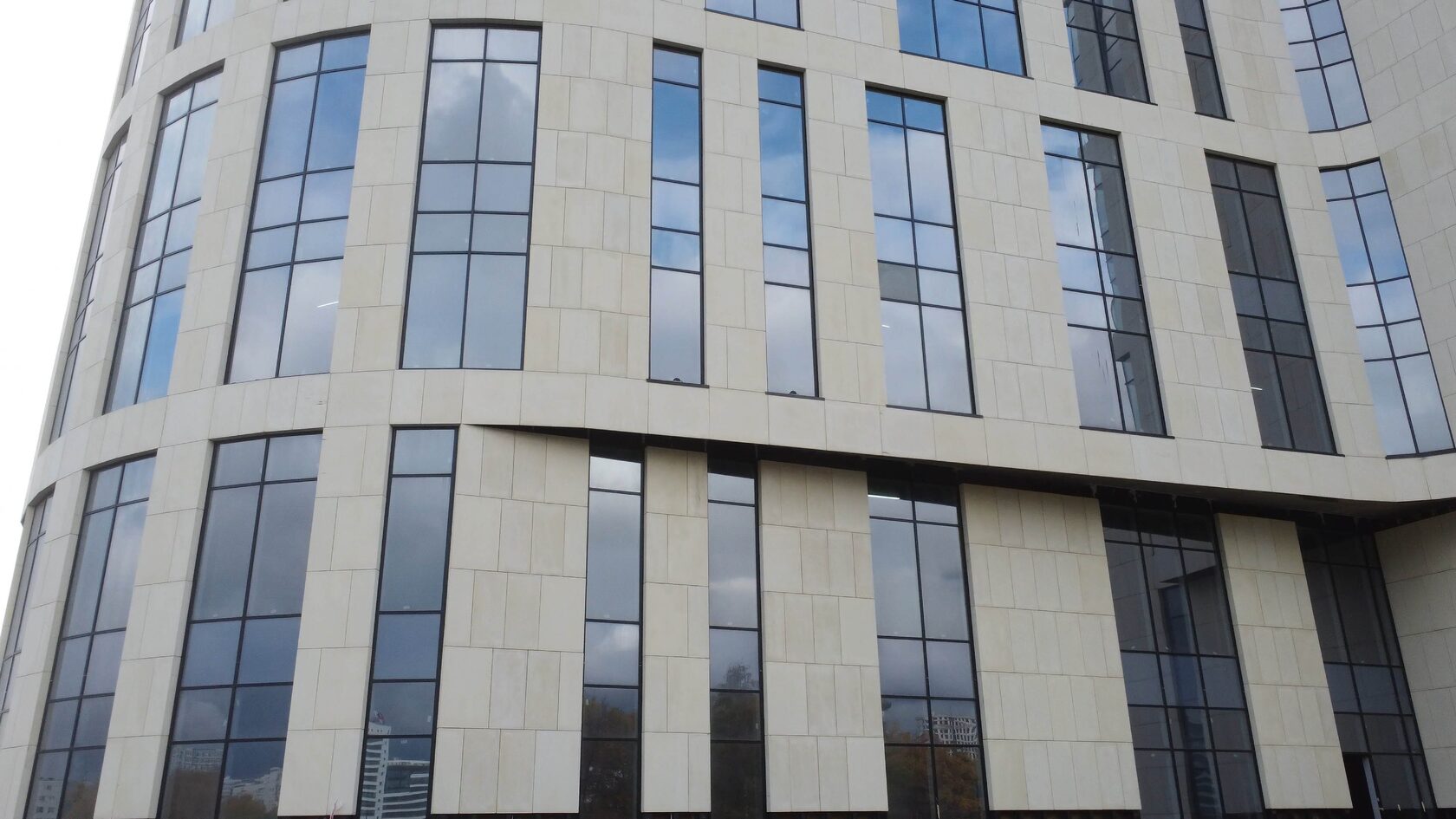
Claddings of different weight on the same building require separate calculations. Among TECHNOFORMA projects this is, for example, the Dinastia club house in Kislovodsk: 6,000 m² of GFRC, 700 m² of porcelain stoneware and 700 m² of granite — three claddings with different weights and fixing details. Another example is the Zolotye Klyuchi residential complex in Makhachkala: 13 storeys, 3 buildings, 12,000 m² of GFRC, design and installation 2016–2017.
How to verify anchor load-bearing capacity on site is described in "Anchor pull-out testing before facade installation".
FAQ
What is the bracket spacing in a rainscreen facade?
It is determined by calculation for each facade zone. The guideline for the typical zone is around 0.6–1.2 m vertically, less at corners and parapets.
How does a load-bearing bracket differ from a support bracket?
A load-bearing bracket takes the cladding weight and wind; a support bracket takes only wind load, and the rail is fixed to it with freedom of movement.
Which standard determines wind load on a facade?
In Russia, code of practice SP 20.13330 "Loads and Actions", taking into account wind zone, height, terrain type and aerodynamic coefficients.
Can bracket spacing be taken from the system catalogue?
The catalogue gives guidelines for typical conditions. A specific building needs a calculation with the real cladding weight and anchor test results.
Why are fixings closer together at building corners?
At corners and parapets, peak wind suction is considerably higher than in the typical zone, so the load on brackets and cladding is higher.