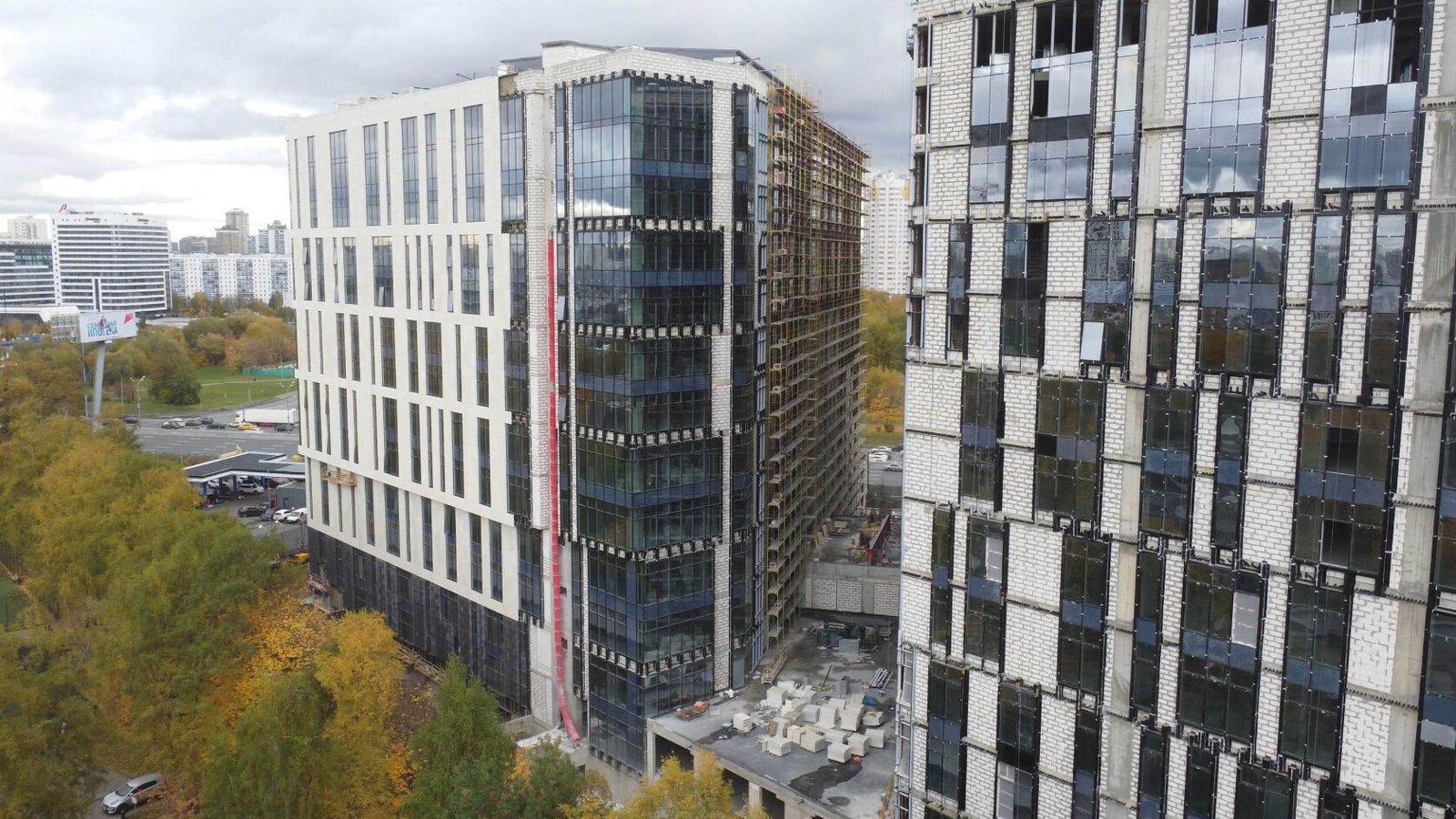
Rainscreen Facade Junctions with Windows and the Roof
Rainscreen facade junctions are the places where the cladding system meets windows, the roof, the plinth, building corners and other structures. This is where leaks, thermal bridges and visual defects most often occur, even though junctions account for a small share of the facade area.
A good junction performs three functions at once: it protects the insulation from water, keeps the cavity ventilated and maintains neat cladding geometry. Each cladding type (porcelain stoneware, profiled metal sheet, stone, glass fibre reinforced concrete) is detailed in its own way, but the principles are the same.
This article is for designers, site managers and technical supervisors. The general build-up of the systems is covered in Ventilated rainscreen facades.
Window reveals
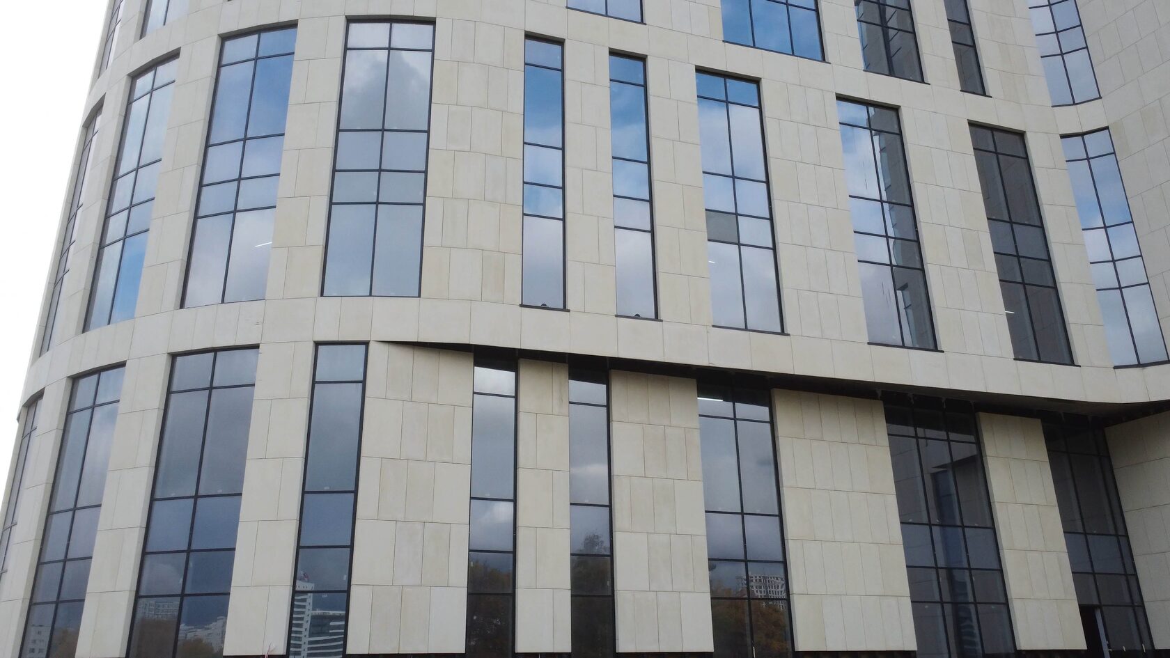
Window reveals are the most common and most problematic rainscreen facade junction. The window sits in the plane of the wall, while the cladding is set out by the depth of the insulation, cavity and substructure; this "well" has to be closed around the whole opening.
• The sill projects beyond the face of the cladding, with a drip, an outward fall and upturned ends; beneath it the insulation has waterproof protection.
• Side reveals and head are made of polymer-coated galvanised steel, aluminium or cladding elements, with insulation inside so that no thermal bridge forms along the frame.
• Fire protection: current Russian fire safety codes (SP) require the surrounds of openings in a rainscreen facade to prevent fire spreading into the cavity; reveals are usually made of steel and fire barriers are installed.
• The joint between frame and reveal is sealed while allowing for thermal movement.
On facades with ornament, the reveal is complemented by a GFRC window surround, pediment or keystone; the element is fixed to the substructure or to the wall with its own brackets.
Reveal depth needs separate consideration. If the window is in the middle of the wall and the facade build-up is thick, the reveal becomes deep, which can be noticeable from the room as reduced daylight. Sometimes windows are moved closer to the outer face of the wall and projected on brackets into the insulation zone; this is decided at the design stage together with the frame fixing detail.
With natural stone cladding, reveals are often made from the same stone: side slabs are fixed on separate brackets, and the head slab gets additional restraint against falling, since it works in tension.
Parapet
The parapet is where the facade meets the roof. Two waterproofing systems join here, and mistakes show up immediately: leaks on upper floors, wet insulation, streaks on the cladding.
• The top of the parapet is covered with a coping sloped towards the roof, with overhangs and drips on both sides.
• The roof membrane is turned up the inner side of the parapet and secured under the coping.
• The top of the ventilated cavity is left open for air to escape but protected from direct water entry.
• If the parapet is crowned by a GFRC or stone cornice, its top surface is designed with a fall and a flashing, and its fixings are designed for wind suction, which is greatest at the top of the building.
If the roof has anchors for facade cradles or guardrails, their fixings pass through the parapet; these penetrations are also drawn in the detail and sealed. Otherwise, the waterproofing will have to be opened up to install a cradle on a finished roof.

Plinth
The plinth is the bottom junction of the facade, where the system meets the paving or the below-ground part of the building. Three things matter here:
• The cavity air inlet is closed with a perforated profile against rodents and debris without blocking air movement.
• Protection of the insulation from splashes and snow: a plinth flashing, a gap between cladding and ground level, moisture-resistant insulation in the lower zone.
• Mechanical strength: plinth cladding takes the most knocks and loads during cleaning, so granite, basalt or reinforced panels are used here.
The plinth is often emphasised architecturally with rustication, darker stone or a projection, in which case the transition from plinth to wall also becomes a decorative band.
Corners
Building corners are zones of increased wind load: substructure design uses higher values for corner areas than for the main field. This leads to practical rules:
• the spacing of brackets and cladding fixings near corners is reduced according to calculation;
• external corners are finished with corner cladding pieces, a butt joint with a profile or a special corner piece in the same material;
• for GFRC, one-piece corner panels are convenient: they close the corner without a visible joint and resist chipping better;
• internal corners are designed with a gap for thermal movement.
| Junction | Main risk | Key solution |
|---|---|---|
| Reveal | Water and fire in the cavity, thermal bridge | Steel surround, sill with drip, insulated reveal |
| Parapet | Leaks from above, wind uplift | Sloped coping, roof membrane upstand, designed fixings |
| Plinth | Splashes, rodents, impacts | Perforated profile, robust cladding |
| Corner | Increased wind load | Reduced fixing spacing, corner pieces |
Common mistakes
Mistakes that technical supervisors see on site most often:
1. The sill does not project beyond the cladding or has no drip, so water runs down the facade and into the cavity.
2. Reveals made of combustible materials or without fire barriers, which breaches fire safety requirements.
3. Insulation stops short of the window frame, causing a thermal bridge and condensation on the inside of the reveal.
4. The ventilated cavity is blocked at the plinth or parapet, so the insulation cannot dry out.
5. The same bracket spacing across the whole facade without allowing for corner and top zones.
6. Decorative elements are fixed only to the cladding rather than to the substructure or wall.
7. Junctions are not drawn in the working documentation and are improvised by installers on site.
All of these problems are eliminated at the design stage: the working drawings must include details for each type of junction, specifying materials and fixings.
Examples from TECHNOFORMA projects
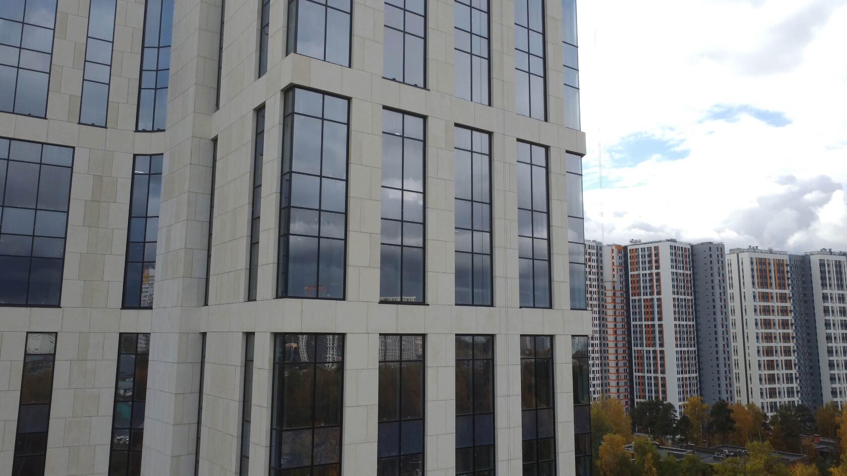
On TECHNOFORMA projects, junctions are detailed by the company's own design department (12 designers led by 2 architects), and installation is carried out by its own installation team. An example of a combined facade where porcelain stoneware and GFRC meet on one building is the Dominanta residential complex in Makhachkala: 14,000 m² of GFRC and 13,000 m² of porcelain stoneware. At the Dinastiya club house in Kislovodsk, 700 m² of granite was added to these materials.
Other projects are in TECHNOFORMA projects. How to integrate cables and luminaires into junctions is covered in Architectural lighting of facades with ornament.
FAQ
How is a rainscreen facade joined to a window?
The opening is framed with steel or cladding reveals with insulation inside, a sill with a drip projecting beyond the cladding at the bottom, and fire protection of the cavity around the perimeter.
How do rainscreen details differ for porcelain stoneware and profiled metal sheet?
The principles are the same; the fixings and trims differ: porcelain stoneware uses clips and separate reveal pieces, profiled sheet uses flashings made of the same metal.
Where can I get rainscreen facade details in DWG?
Substructure manufacturers publish standard details. For a specific building, details are developed in the working documentation, taking the cladding and substrate into account.
Is a fire barrier needed around windows in a rainscreen facade?
Yes. Current Russian fire safety codes require openings to be protected against fire spreading into the cavity; the solution is built into the detail.
Why does a ventilated facade leak around windows?
Most often because of a short sill without a drip, a poor joint between sill and reveals, or missing seals between the frame and the surround.